

ST recently released four new VIPERGAN devices, the VIPERGAN50W, the VIPERGAN65W, the VIPERGAN65D, the VIPERGAN100W, and the VIPERGAN100WB. They are all very similar to VIPERGAN50, VIPERGAN65, and VIPERGAN100, except that they use a 700 V gallium nitride (GaN) transistor, whereas the previous models used 650 V transistors. Additionally, the VIPERGAN65D and VIPERGAN100WB offer a higher current limit to accommodate applications that require more headroom at startup. The VIPERGAN65D also uses a different packaging. And since both VIPERGAN and VIPERGAN W series are pin-to-pin compatible, designers can migrate to the new components with minimal to no design or code changes, enabling new applications and improved performance.
Where we started and how it’s going
More choices for a broader range of applications
Avid readers of the ST Blog will remember that we first talked about the VIPERGAN series in 2023. The devices offer a broad output power range (50 W to 100 W) and a wide operating voltage range (9 V to 23 V). We also launched the EVLVIPGAN100PD, our first VIPERGAN100 evaluation board for USB-PD application. VIPerGaN devices consume less than 30 mW in standby mode with adaptive burst mode enabled. Their QFN 5 mm x 6 mm package also makes them among the smallest devices in the industry for this level of power output. As a result, it led to numerous design-ins and design-wins, from air conditioners to industrial automation and consumer appliances.
More flexible design processes
Today’s devices build on the previous generation to offer a more powerful GaN transistor, enabling designers to develop new products that take advantage of the wide bandgap material. We are also releasing the EVLVIPGAN50WF, EVLVIPGAN65WF, EVLVIPGAN65DF, EVLVIPGAN50WP, EVLVIPGAN65WP, and EVLVIPGAN100WP development boards to help teams get started faster and enjoy a reference design that can shorten their time-to-market. These boards and the VIPERGAN W reflect the feedback we got from customers of the first VIPERGAN. While the response has been overwhelmingly positive, some applications require higher voltage. That’s why we are using a 700 V transistor and created the VIPERGAN100WB for those who want to push our most powerful VIPERGAN model further.
More designs with one device
The great output power is possible thanks to a GaN transistor with a lower RDS(ON) (470 mΩ for the VIPERGAN50W, 290 mΩ for the VIPERGAN65W, and 270 mΩ for the VIPERGAN65D and VIPERGAN100W(B)). The VIPERGAN100W will only provide an output power of 100 W in the European voltage range (185–265 VAC) or with PFC use. Otherwise, it will provide 75 W (85–265 VAC). Moreover, all devices are pin-to-pin compatible, so engineers can rapidly swap them without significantly altering the PCB layout or design. Our teams thus hope to lower the barrier to entry for GaN by offering a more practical product portfolio.
Why a QR ZVS Flyback Converter?
Applications keep requiring greater power density
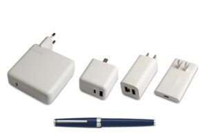
In our application note AN1326 (L6565 Quasi-Resonant Controller) from November 2002, we explained that engineers often used quasi-resonant (QR) zero voltage switching (ZVS), also called valley switching at turn-on, in the switched-mode power supply (SMPS) of TVs and other appliances. While still true today, the topology is now in a lot more products. The reason is that power envelopes have gotten significantly denser with each passing decade. For instance, TVs now push more pixels while having even more stringent power consumption requirements. Similarly, while 50 W chargers are not new, consumers demand supplies that don’t look and feel like giant hot bricks and fast-charge laptops, tablets, phones, and more.
QR ZVS Flyback converters keep needing greater efficiency
The industry often turns to QR converters because of their efficiency. In traditional PWM converters, the device turns on when the voltage is at its highest, which causes power losses that are compounded as switching frequencies increase. Engineers can mitigate this with a snubber circuit, but the best way to improve efficiency is to soft-switch, meaning to switch when the voltage, or current, is at zero. To do that, a resonant (inductor-capacitor or LC) transforms the square-shaped signal into a sinusoidal waveform. In ZVS, turn-on happens at the bottom, or valley, of the curve. Over the years, engineers attempted to improve the efficiency of QR ZVS flyback converters, and GaN just gave them a new answer.
Why VIPERGAN50W, VIPERGAN65W/D, or VIPERGAN100W(B) Today?
The GaN transistor
The VIPERGAN50W, VIPERGAN65W/D, or VIPERGAN100W(B) use a similar GaN transistor as the MASTERGAN series and thus offer similar benefits. For instance, GaN’s high electron mobility enables devices to tolerate high switching frequencies. Consequently, they can handle greater loads while suffering far fewer losses. GaN thus enables the creation of supplies that can output more power while shrinking their overall footprint. Historically, VIPERGAN50 was the first to come out. Then, ST demonstrated its commitment to GaN by releasing models with greater output power.
The Multi-Mode Operations
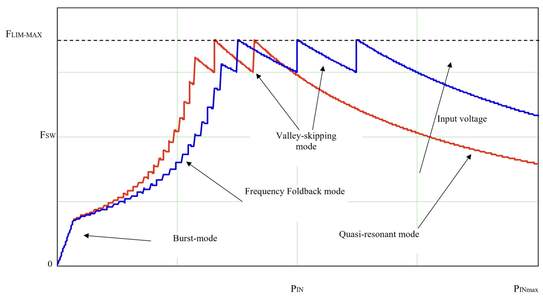
The new devices optimize their performance thanks to multi-mode operations. In a nutshell, the VIPERGAN50W, VIPERGAN65W/D, and VIPERGAN100W(B) adjust their switching frequencies based on their load. During a heavy load, the quasi-resonant circuit synchronizes the GaN turn-on with the transformer demagnetization (ZCD pin) to minimize losses. Similarly, a heavy or medium load will trigger valley-skipping. In a nutshell, the transistors can skip one or more valleys when the load decreases. In this scenario, the switching frequency decreases to limit losses.
Similarly, the frequency foldback mode lowers the frequency during medium and light loads but ensures it remains above a certain threshold to prevent noise. Finally, burst-mode, at light or no load, can limit the switching frequency to a few hundred hertz while keeping a constant peak current to prevent noise. In this last mode, the VIPERGAN50, VIPERGAN65, and VIPERGAN100 have a quiescent current of only 900 µA. The new devices can thus help meet new environmental regulations that demand greater power efficiency to save global resources.
The protection features
Traditionally, engineers add external devices to provide safety features. The fact that VIPERGAN50W, VIPERGAN65W/D, and VIPERGAN100W(B) vastly increase efficiency means ST had room to include more safety functionality. Designers thus need fewer components on their boards, reducing their BOM. For instance, the new devices are the first in the VIPer Plus series to offer input overvoltage protection (iOVP) to protect against sudden voltage spikes. Similarly, the brown-in/brown-out feature monitors the supply voltage to shield the system against unreliable mains by setting the minimum input voltage that will start operations and the minimum one that will stop it. And these features are on top of more common over-temperature and overload / short-circuit protections.
How to get started?
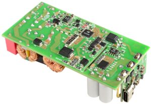
The best way to get started is to grab one of the evaluation boards. They come with five power delivery profiles: 5 V at 3 A, 9 V at 3 A, 12 V at 3 A, 15 V at 3 A, and 20 V at 5 A. Hence, teams get a hardware platform with schematics to jumpstart their custom PCB and profiles that will be close to what they will use in their application. The system has a peak efficiency of more than 90%, even at 50% of the load, whether at 115 V or 230 V at the mains. The board also uses a power factor correction system based on an L6564 to limit distortions.