

eDesignSuite Power Management Design Center is more than just a new console, but a new way to choose more responsible products, simulate higher loads, and shave weeks off the design phase of power circuits. The suite includes a power supply and LED lighting design tool, a digital workbench, and a power tree designer. Concretely, ST is now supporting 30 kW applications, and users can expect support for even greater power solutions as we update our web application. Put simply, engineers have access to new customization and simulation capabilities, which expand the scope of the Power Management Design Center and lower the barrier to entry for power application design.
eDesignSuite Power Management Design Center: New console
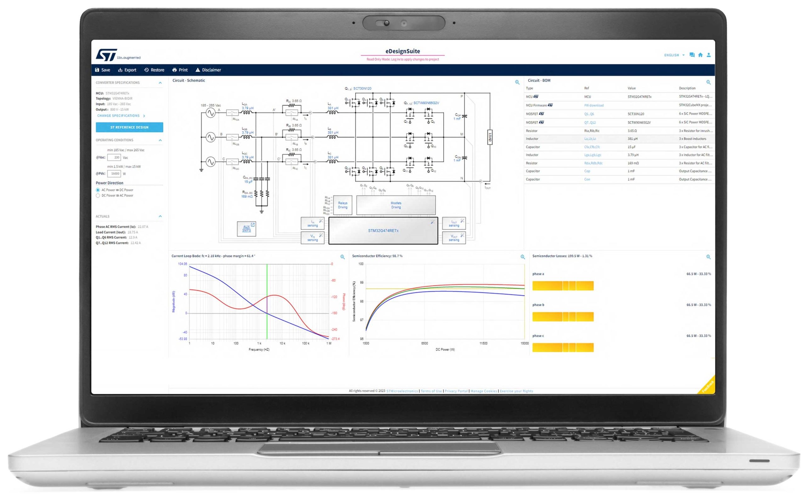
Users will instantly be familiar with the new console of the Power Management Design Center because it remains extremely close to the version ST launched when we moved to HTML 5. After all, its intuitiveness is a key component for engineers working on complex power applications. What has primarily changed is that we are now offering the ability to highlight devices considered “responsible”, meaning they enhance energy efficiency. Behind the scenes, it required us to create new categories and labels, update our databases, and determine which devices would have the most significant impact on a design. For users, all it takes is a single click to know how to optimize their design meaningfully.
And this is just the beginning. We are already working on providing impact simulations to ensure designers can concretely see how choosing a responsible device affects their design. Too often, engineers recognize that a gain of just one percentage point in efficiency can make a significant difference. Unfortunately, communicating this fact can be as tricky. That’s why we are working to make eDesignSuite a scientific witness of what it means to design with responsible solutions, such as helping determine the amount of greenhouse emissions saved and other real-world environmental benefits. In a nutshell, we are taking the simulation engine that has made eDesignSuite so popular and using its rigorous models to make “responsible” a lot more tangible.
New topologies
The Digital Workbench in eDesignSuite Power Management Design Center got support for new topologies that primarily focus on energy storage. Interestingly, some topologies exhibit bidirectional behavior, playing a crucial role in designing systems that not only supply power to battery chargers, such as those in electric vehicles, but also enable power to be fed back to the grid or homes, as seen in Vehicle-to-Grid (V2G) and Vehicle-to-Home (V2H) applications. These new topologies are especially promising when working with gallium nitride or silicon carbide. Their arrival in Digital Workbench means that engineers can now use our wizard to expedite their development and more accurately size the other components of their design, among other benefits.
ST will continue to innovate by introducing advanced topologies. Recently, we launched a 7 kW two-channel multilevel buck converter and a 10 kW two-channel multilevel boost converter, both featuring Maximum Power Point Tracking (MPPT), which aids in designing for solar applications. Indeed, as solar energy is a volatile source due to frequent fluctuations caused by the sun’s movement or clouds, it is imperative to track these changes to optimize power conversion. That requires an MCU like the STM32G4 and a topology capable of handling these constraints. By offering such new topologies in Digital Workbench, engineers can significantly reduce their time-to-market.
New electro-thermal simulation
The fact that we are supporting new topologies and offering a new console highlights the unique demands engineers are facing. As markets require more efficient systems, simulations are ever more critical. That’s why eDesignSuite also got a new electro-thermal simulator, the so-called PCB Thermal Simulator. In a nutshell, it opens the door to temperature analysis based on the electrical performance of a PCB by simply analyzing Gerber files.
Specifically, by using a precise thermal model and iterative calculations, the ST PCB Thermal Simulator quickly and precisely estimates temperatures on both sides of the board. It can also simulate inner layers and allows manual or automatic placement of heat sources (custom or predefined devices), heat sinks, copper areas, and thermal vias. Simulation results are displayed as colored maps overlaid on both sides of the board. Users can inspect any point for temperature values and export results as CSV files. Hence, while the first applications of the electro-thermal simulator primarily focused on motor control, others are now starting to adopt the technology, and we are ensuring that more industries can benefit from it.