Our Power Schottky & FERD eTool is the first solution in the industry to offer a simple and straightforward way to perform power losses calculations to help engineers choose the best Schottky or Field Effect Rectifier Diodes (FERD) for their design. The eTool lives in the Smart Selectors section of eDesignSuite, and it primarily targets engineers working on Switched-Mode Power Supplies (SMPS), as well as decision makers trying to understand the rationale behind the selection of various components.
The tool’s ultimate goal is to present the user with a graph of the losses of a diode over a wide range of temperatures, with the possibility of exporting it as a picture or extracting all its data points to manipulate them. It’s also the only tool on the market today capable of quickly computing the evolution of power losses according to the junction temperatures of specific components. This feature is essential because it enables users to track how the leakage current of Schottky and FERD devices influences their thermal behavior. As a result, this approach has the merit of substantially reducing the risk of a human error while offering instantaneous feedback.
Schottky vs. FERD
This tool is one of the hidden gems of eDesignSuite. Most engineers are familiar with the schematics and simulation aspects of the software, which removes some of the complexity of designing an application. For instance, our Smart Transformer Selector can automagically insert a transformer into a design and dynamically change some of its components to optimize the system. The Power Schottky & FERD eTool is part of eDesignSuite to help professionals in their decision-making process as they try to evaluate whether it might be better to use a FERD or stick with a Schottky diode. The latter is popular because it has a low forward voltage drop and it can work at high frequencies. They are also familiar, and our new models using a SOD123Flat or SOD128Flat package continue to penetrate the industrial and automotive industry. However, our Field-Effect Rectifiers have outstanding characteristics.
Many engineers still don’t automatically think of using them, but they represent an answer to today’s challenges. They have an even lower forward voltage drop and a lower leakage current, especially at high temperatures, which means it’s possible to create a denser power supply and meet more stringent standards, like Energy Star 6.0, which makes them a game-changing component, especially when it comes to smartphones or laptop chargers. However, there are cases, especially for very low and very high power applications, where Schottky diodes can sometimes be more advantageous. A FERD offers a favorable price-to-performance ratio, but it isn’t a universal substitute. It is thus vital for engineers to open their design to all possibilities to get the best efficiency possible, and better grasp the compromises as well as the advantages of each solution. This is why we created the Power Schottky & FERD eTool.
Let’s Build a Laptop Adapter

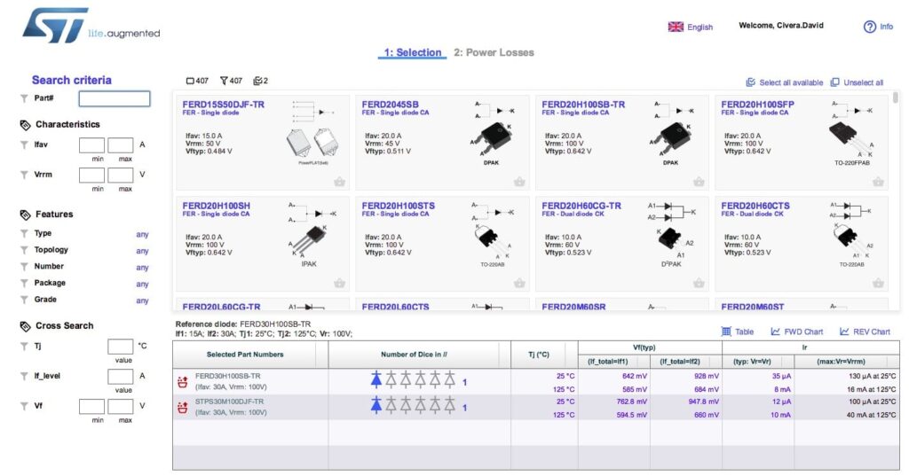
Once users open the eTool, by selecting Smart Selectors from the home menu, they get the tool’s home screen, with the top center panel showing a series of Schottky diodes and FERD. Let’s simulate a team of engineers building a 45 W laptop adapter with a 19.5 V / 2.31 A output and who is trying to decide what component to use. We are therefore going to select the FERD30H100SB and the STPS30M100DJF-TR (Schottky) by clicking the basket symbol at the bottom right of the product listing, which will automatically drop the component into a table below.
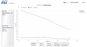
At this point, we can select the 2: Power Losses category at the top of the screen and follow the two steps that present themselves to the user. Clicking the plus sign underneath the first step – next to App Waveforms – will offer the various waveforms of an SMPS. For this example, we can select Triangle Left, located at the bottom left of the new panel.

The second step is also quite straightforward since we have to click the plus sign next to Simulations List, then click on Insert a waveform and select App_, the automatic name of the waveform that we created earlier. We can then select the first part number (FERD30H100SB) and call the simulation name “FERD”, then click “OK”. We then create another simulation that we’ll call Schottky, and that will use the same waveform, but the other part number (STPS30M100DJF-TR). Finally, clicking the two-arrow sign on the right will produce the power loss graph. In this example, we see that the power losses of the FERD device are vastly inferior to those of the Schottky alternative.
Power User Features

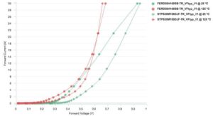
The exceptional ease of use of the eTool hides numerous power features that go beyond this simple example. For instance, once the system creates a graph, it’s easy to generate other curves to compare the power losses for the maximum forward voltage drop of each component, or the losses for the typical reverse current, among others. It is also possible to compare the forward voltage drop and reverse current leakage of these two components by selecting these graphs in the first page and to adjust them on the fly to show performance under maximum conditions or specific temperatures, thus opening engineers to the visualization of a myriad of data points. Currently, the system allows users to compare up to five diodes. Additionally, we update the database approximately four times a year, meaning with each major release, to ensure users have up-to-date information.
The Power Schottky & FERD eTool also offers various ways to find the components that may suit a particular design. If users already know the part number, they can enter it and find what they’re looking for instantaneously. However, in most cases, engineers must work around particular characteristics, which is why they can fill up current and voltage ratings, topology, packages, forward voltage drops, junction temperature, and even grade-level, among others, and the system will sort out the relevant options. This level of granularity helps designers focus on the performance they are hoping to achieve, rather than what’s available in their catalog. Finally, once they have the right component, they can enter its part number in eDesignSuite to integrate it in their schematics.
Your New Secret Weapon
The eTool is probably one of the most underrated solutions of the eDesignSuite platform given the impressive level of performance it offers. Engineers can even create their custom waveform to more accurately simulate achievements in their design, and they have access to data sheets and product pages to limit the need to leave the application when they are searching for information. Furthermore, they no longer have to manually perform computations to understand how these diodes will behave under various conditions, which could be a daunting task because of the amount of information to process and the formulas to remember. We are also continuing to make the eTool more accessible and now offer a translation in Chinese. Finally, power users will undoubtedly want to check the User Manuel by clicking the question mark at the top right of their screen.
