The STNRGPF01 is a new three-channel interleaved Continuous Conduction Mode (CCM) Power Factor Correction (PFC) digital controller from ST. Customers often underestimate the work that goes into designing a power supply. Very few, if anyone, will turn an appliance on and marvel at how mind-blowing (pun intended) it is. Yet, a poor one could cause serious harm or prevent a product from getting the regulatory approvals needed for commercialization. For instance, the international standard IEC 61000–3–2 limiting the harmonic emissions in appliances has made PFC controllers an increasing necessity. Hence, ST’s component distinguishes itself by combining the company’s experience in power management and circuit design to offer impressive features and an amazing integration with eDesignSuite.
Getting Closer to a Power Factor of 1

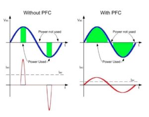
In Switched-Mode Power Supplies (SMPS) of 1 kW or more, a poor design could seriously impact performance and increase power losses, which can quickly blow up operating costs. One way to quantify this is to use the Power Factor (PF), the ratio between the real or working power used to run the device (in kW), and the total or apparent power actually supplied (in kVA) (PF = kW/kVA).
In a perfect world, the PF would always be one, meaning the real and apparent power are exactly the same, and devices would only use what they need. In real life, there’s always some non-working power or reactive power, meaning power that is supplied, but not used to run the device. This is especially a problem for big appliances, electric motors, transformers, or welding set, among many others. One reason is that a design will almost always use some overpowered components to ensure they can handle all their tasks. A design with absolutely no headroom would be irresponsible. However, this is translated into reactive power, meaning power that isn’t directly doing any work but costs money.
Continuous Conduction Mode (CCM) vs. Discontinuous Conduction Mode (DCM)
To improve the power factor, as required by the international standards, engineers use Power Factor Correction (PFC) converters. Very simply, inductors store electricity to provide the reactive current needed instead of drawing it at the mains. Hence, a PFC decreases the total or apparent power (kVA) to get closer to a PF of one. Improving the PF also reduces harmonic emissions, which explains why the latest regulations have increased the popularity of PFCs.
The STNRGPF01 is primarily dedicated to an SMPS of 1 kW or more, and thus is designed for converters that run in Continuous Conduction Mode (CCM). Very simply, this means the current continues to flow through the inductor and never reaches zero during the different switching cycles. On the contrary, the Discontinuous Conduction Mode (DCM), more popular in DC-DC converters, works by allowing the inductor current to drop to zero. However, in high SMPS, DCM would cause more conduction losses and more stress on the PFC-MOSFETs, because of higher peak and RMS current, reducing the efficiency. Hence, it’s easy to understand why these SMPS require CCM.
STNRGPF01: The Best of Both Digital and Analog, All-In-One

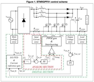
STNRGPF01 can control PFC converters that use up to three interleaved channels, meaning that it will use up to three stages in parallel. Designers can, therefore, use smaller inductors, and thus maintain smaller dimensions, while delivering greater output power. However, the circuit management becomes much more complex because all channels must have the same amount of current. As a result, digital controllers are the “weapon of choice” for tackling this issue. This is the reason why the STNRGPF01 includes a digital control section, which simplifies current balancing and the rest of the board’s management, such as the implementation of the cooling functions or thermal protections.
However, the key feature of ST’s component is that it also contains an analog controller, which ensures a better control of the average current, cycle by cycle, for a faster dynamic response. Hence, although it has all the advantages of a digital device, like the ability to customize the design according to the platform’s needs, engineers can manage the controller as if it was an analog one, without knowledge of its internal architecture. In other words, designers have the high performance of an analog control and the amazing flexibility of a digital section, all under one roof. Designing a powerful PFC converter with features like voltage control, OCP (Over-Current Protection), OVP (Over-Voltage Protection), and temperature protection has never been easier.
Evaluation Board EVAL-IPFC01V1

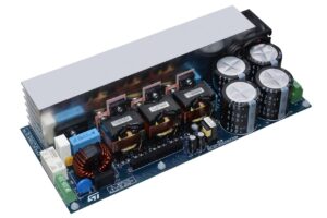
A recurring theme on the blog is that ST isn’t simply a component manufacturer, but a company that goes far beyond what the competition offers to help engineers make the right choices and quickly reach optimal designs. As a result, the company doesn’t only provide one of the most feature-rich PFC controllers on the market, it also offers an evaluation kit based on the STNRGPF01, the EVAL-IPFC01V1, to greatly accelerate developments. This 3 kW three-channel interleaved PFC is composed of a power board, a control module, and an adapter. It is thus the easiest way to start developing a power supply that will meet the IEC 61000–3–2 standards.
Furthermore, to quickly transition from the development board to the final product, ST offers a free dedicated software tool called eDesignSuite. Thanks to a simple and practical Graphical User Interface, designers can customize the settings of their STNRGPF01 by entering the PFC converter’s specifications. The system will even provide default values to speed the process, and the software can generate the binary for the component, so engineers can load the firmware without having to type a single line of code. All the options are further explained in the application’s documentation.
To know more about PFC controllers or start using eDesignSuite, please visit ST’s website.
