CLT03: To improve the accessibility of our content, please find the audio version of this blog post.
Too often, companies forget that industrial applications are also getting smaller and denser. While many understand why consumer products pack more features, industrial control systems aren’t exempt from such trends. Hence, ST launched the CLT03-1SC3 and CLT03-2Q3, two current limiters for digital inputs that vastly reduce heat dissipations. They are also compatible with applications that do not require an optocoupler, such as low voltage outputs, without the need to use additional components. As a result, it becomes easier to build more cost-effective factory automation solutions. Similarly, engineers can miniaturize building automation systems or drive motors more efficiently. The CLT03-1SC3 and CLT03-2Q3 have similar specifications but support single and dual channels, respectively. As safety regulations limit the number of channels, offering only one or two gives engineers more flexibility and tinier packages.
The Challenges Behind Digital Input Current Limiters
Microcontrollers and network modules get a lot of the limelight. However, without a safe and robust digital input circuit, it’s impossible to know which way is up, sometimes literally. It’s the reason why IEC61131-2 strictly regulates the 24 V industrial sensors that help determine if a signal qualifies as a 0 or a 1. For example, an industrial sensor needs to send data to the MCU. Its signal will go through the digital input interface, which will help determine if the MCU should interpret the signal as a “0” or a “1”.
A “0” in an IEC61131-2 Type 1 sensor must be between -3 V and +15 V at 15 mA. A “1” is between 15 V and 30 V, with a current between 2 mA and 15 mA. In a Type 3 sensor, a “0” has a voltage between -3 V and +11 V at 15 mA. A “1” has a voltage between +11 V and +30V at a current between 2 mA and 15 mA. The CLT03-1SC3 and CLT03-2Q3 support both Type 1 (legacy) and Type 3 (modern) sensors.
Current limiters for digital inputs face many challenges. For instance, they must deal with high voltages in harsh environments. Engineers know that many 24 V loads suffer from drastic spikes. Additionally, the limiter itself must output very low currents and remain compatible with the voltages of low-power microcontrollers. As a result, original digital inputs used a discrete system, and many still use optocouplers. As circuits got smaller, engineers had to find a way to shrink their design. The CLT03-1SC3 and CLT03-2Q3 allow them to miniaturize thanks to the ability to remove components and optimize their system.
CLT03-1SC3 and CLT03-2Q3: Miniaturization Through Reductions
Dissipating Far Less Heat
The most common issue discrete current limiters face is their inherently high power and heat dissipation. A Type 3 digital input must have a current as low as 2 mA. Hence, the drastic reduction in current traditionally means high losses. Indeed, while it is possible to use passive resistors to reduce the current, their performance linearly tracks the voltage, which leads to increased losses and, therefore, significant heat dissipations. Additionally, a discrete current limiter itself consumes more than 2 mA. The CLT03-1SC3 and CLT03-2Q3 thus offer much better performance because their mechanisms aren’t linear with the voltage. As a result, they do not suffer the same power losses and heat dissipation issues.
Powering Itself and Using Small Packages
Another way the CLT03-1SC3 and CLT03-2Q3 help shrink a design is through their self-powered capabilities. Indeed, it is possible to activate both current limiters with the input signal. Moreover, they consume no power at all in their off state. Engineers do not need to use a power supply to drive them and can, therefore, improve overall efficiency. Additionally, since the programmable logic controller must have light indicators, the architecture can drive LEDs without additional boards and connectors. The CLT03-1SC3 and CLT03-2Q3 are one of the few self-powered digital input current limiters on the market today. Finally, the fact that the two-channel CLT03-2Q3 is available in a tiny QFN package means engineers can make their PCB even smaller.
Working with Isolated and Non-Isolated Systems
Teams can also further shrink their design thanks to optimizations within the digital input current limiter and benefit from a more versatile system. Indeed, while many engineers look at basic specifications, studying the overall architecture is as critical. For example, ST modified the output stage of the CLT03-1SC3 and CLT03-2Q3 to ensure their usage in isolated and non-isolated solutions. Teams use an optocoupler to isolate the field side from the logic side. In a harsh industrial environment, isolation is necessary to send a clean signal and protect the programmable logic controller. However, there are situation when an optocoupler isn’t necessary such as when working with low-power microcontrollers. In such a case, the ST current limiters can drive the digital input without any additional external components, thus further simplifying the PCB.
CLT03-1SC3 and CLT03-2Q3: Quality of Life Improvements Through Innovations
60 V And Reverse Plugin
To make the CLT03-1SC3 and CLT03-2Q3 more robust, we ensured support for an input voltage of up to 60 V while still supporting reverse plugin. Traditionally, digital inputs sustain up to 45 V. However, an increasing number of safety applications aim for 60 V. Industrial settings are often unstable. Hence, allowing for a greater headroom makes the system more robust. However, competing digital input current limiters rated at 60 V don’t support reverse plugin.
Programmable Test Pulse Generator
ST engineers wanted to help customers monitor their system better. As a result, we included a configurable test pulse generator. The idea of a test pulse itself isn’t new. Traditionally, it takes the form of a flag. If a device enters a fault region, it raises a flag to the microcontroller. Unfortunately, if the sensor doesn’t send information, there’s a possibility that input might be stuck to the high voltage position, or 1. The MCU doesn’t have any way of knowing whether the output is erroneous, which may lead to errors.
To solve this issue, the CLT03-1SC3 and CLT03-2Q3 can send a programmable test pulse that can regularly force the input to 0. It thus offers a way to check if the high voltage is a result of sensor information or just an error due to a fault. Additionally, if the input voltage climbs above the IEC61131-2 specification, meaning above 30 V for DC 24V input signal applications, it is possible to put our digital input current limiters in a safe mode to reduce the current. The device then returns to a normal behavior once the voltage decreases.
Next Step

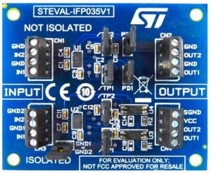
The best way to try the CLT03 family of devices is to grab the STEVAL-IFP035V1. The evaluation board uses two CLT03-2Q3s to allow engineers to test isolated and non-isolated inputs. It is thus the quickest way to witness the lower heat dissipation or the devices’ EMI robustness. Indeed, competing digital input current limiters don’t use EMI filters because they limit the data rate between the sensor and the microcontroller. However, since sensors inherently have a low data rate, our engineers decided to include a high-rated EMI filter. Its presence in CLT03 devices helps further reduce the bill of materials since they improve the overall robustness.
