To learn more about our power devices, we have a webinar covering our wide catalog.
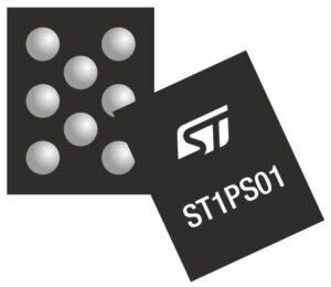
The ST1PS01 is a 400 mA nano-quiescent step-down converter capable of receiving an input voltage ranging between 1.8 V and 5.5 V while offering an ultra-low-voltage output. There are various members of the ST1PS01 series, as we detail in the table below. In each case, a component has four output voltages that a microcontroller can dynamically select at any moment through two digital I/O pins, thus making it a truly flexible converter capable of adapting itself to the new low-power MCUs that are breaking records with ever-decreasing consumptions. Its size of only 1.11 mm x 1.41 mm and its 94 % efficiency at one mA load makes it an excellent choice for small products that rely on a battery. To achieve such results, we designed a new architecture that prioritized innovations and flexibility.
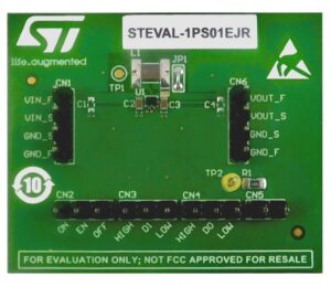
[table id=2 /] With eight variants, the ST1PS01 offers more output voltage options than any other competing products in the industry. Its wide range can go as high as 2.8 V for the ST1PS01A and as low as 0.625 V for the ST1PS01H, which is the lowest output voltage in the industry for this type of device. The A, D, and E versions are already available while the rest of the family will reach distributors by the end of the first half of this year. The deployment of the entire series is rapid, thus offering designers the possibility of quickly testing the new devices. There are also evaluation boards available to test each converter’s characteristics and more promptly integrate them in a final design.
The 3 Motors of Flexibility
1. Digitally Selected Output Voltages

It’s easy to overlook the importance of being able to select the output voltage digitally, but it’s one of the pillars that give this new architecture such flexibility. The datasheet of the ST1PS01 provides developers the pin setting for each output voltage. The microcontroller has to drive the pins D1 and D0 to select one of the four different values available. It is thus effortless to adjust the output voltage to switch to a low-power mode when the system is falling asleep, or to tweak the step-down converter to fit the needs of various tasks and optimize the overall power consumption. The consequence of such implementation is that engineers really shouldn’t leave the D1 and D0 pins floating but precisely drive them according to the needs of their application.
2. Dynamic Frequencies for Better Efficiency
The ST1PS01 also manifests its flexibility through its dynamic frequency adjustments that enable it to have a notably low quiescent current at no load, while also retaining more than 90 % efficiency over a wide range of load currents (from 0.1 mA to 100 mA), regardless of the output voltage. The presence of its frequency converter does introduce some harmonics, which means that applications that are extremely sensitive to noise will select a component with a fixed frequency. However, our engineers focused on designs that prioritize power efficiency and mobility rather than noise because, for the vast majority of applications, this architecture offers a lot more benefits than a component with fixed frequency.
3. A 100 % Duty Cycle

If an input is unstable and drops to the point that its value becomes very close to the output, the latter also becomes unstable and starts falling. In this case, the ST1PS01 switches to 100 % duty cycle operations to ensure that the output voltage tracks the input voltage. Very simply, the step-down converter turns th regulator off to directly connect the input and output pins through the high-side MOSFET. It means the voltage is nearly the same at the input and output, besides the small drop that occurs in the MOSFET. If the input voltage is higher than the nominal output voltage by only 200 mV or less, the device enters the 100 % duty cycle. If the input voltage picks up again and is higher than the nominal voltage by 300 mV or more, the device leaves the 100 % duty cycle mode and resumes normal operations.
The 3 Advantages of an Innovative Architecture
1. A Different Feedback Loop for Faster Responses
As with all buck converters, the ST1PS01 has a feedback loop that compares the output voltage to a reference. Traditionally, if the output is far from its target, the device throws an error and sends the electrical current back to the power stage to rectify it. However, it requires the presence of a complex compensation module that limits a device’s performance because of its inherently low bandwidth. The ST1PS01 compares the output voltage with the comparators’ thresholds and uses various schemes to end up with a compensation system that’s widely simpler, enabling the creation of a more straightforward device that can respond to transient current a lot quicker. For instance, we use fast and low-power offset comparators, instead of an oscillator, to turn on the high or low side quickly and efficiently to get the desired ripples at light load.
2. A Pulse Frequency Detection Module to Know What to Turn on and Off
The ST1PS01 also decreases the quiescent current and increases its efficiency by using a pulse frequency detection module. When the output current is under a certain threshold, the architecture turns on the high-side, charges the output capacitor, then turns off everything else. Similarly, if the output current is higher than a certain threshold, the device switches to high current mode and turns on all the modules it needs to respond to high transient current. This mechanism is possible because the pulse frequency detection module measures the time between two pulses, which helps determine the output current and whether it is below or above certain thresholds.
3. An Optimized Architecture for a Smaller Bill of Materials

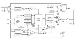
The architectural efficiency of the converter translates into the fact that engineers need a lot less external components to run it. The device’s soft start capability means that designers don’t need to add an external timing capacitor, and its original compensation module signifies that using the ST1PS01 demands just two small capacitors and a 2.2 µH inductor on the PCB. Internally, the architecture also benefits from these optimizations and doesn’t use an oscillator as it’s the comparator that defines the frequency of the commutation, thus enabling rapid changes to the device’s frequency. Our architectural choices also allow us to use a low-power Bandgap/Bias module at the input (see diagram) and a simpler circuit, which lowers the overall power consumption even further.
The ST1PS01 Step-Down Converter in Asset Tracking and More

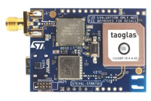
We are already using the ST1PS01 step-down converter on our STEVAL-STRKT01 LoRa IoT Tracker and expect it to be popular among asset tracking solutions thanks to its efficiency and performance at little or no load. These applications spend the majority of their time in a deep sleep mode, so the quiescent current measurement of a component is crucial. ST will also be publishing PSPICE models of the ST1PS01 series this year to help designers better integrate these new components in their design.
- Learn more about the ST1PS01
