This tutorial will walk you through setting up a quick 6LoWPAN (pronounced “six-lo-pan”) network to send data from a node to a gateway connected to a Wi-Fi network. Hence, this demo will help you get a first hands-on experience with ST’s software stack, and development boards. As sub-gigahertz wireless protocols become ever more popular, and companies like Wi6Labs come up with products compatible with many of these standards, setting up a 6LoWPAN network is a great way to begin a project or prototype that aims to take advantage of this new trend.
| To know more about the Function Packs of this tutorial:
|
Step 1: Preparation
The most time-consuming and sensitive step of this tutorial is the preparation. Once you have all the tools at your disposal, getting starting is extremely easy. For this demo, we’ll use a node, and a Wi-Fi Bridge that acts as a gateway to the Internet.
1.1. Shopping
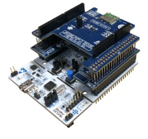
To start, we strongly recommend the following components : two Nucleo-F401RE boards, which will serve as the base for the node and gateway, two X-Nucleo IDS01A5, which are sub-gigahertz expansion boards, then one X-Nucleo IDW01M1 board to connect the gateway to a Wi-Fi access point, and the X-Nucleo IKS01A2, which contains multiple sensors.
All these parts are easily available at many online retailers, and should total about 100 dollars, before taxes and shipping. Hence, this is one of the most affordable ways to start developing sub-gigahertz applications. It is possible to use other boards, but if you are new to the ST ecosystem, we recommend using those exact components, as it will greatly ease your learning curve.
1.2. Downloading
It is imperative that you also download the latest drivers and firmware. If you are using Windows, you will need the STSW-LINK009, which are USB drivers for the Nucleo-F401RE boards. You can go to the dedicated site , and click the link at the bottom of the page to start downloading them. Finally, just open the folder “en.stsw-link009” and click on “dpinstamd64.exe” or “dpinst_x86.exe”, depending on whether you are using a 64-bit or 32-bit version of the operating system.
It is also necessary to download and install the STSW-LINK007 firmware to update your two Nucleo-F401RE. The utilities to flash the boards are available for Windows, macOS, and Linux, and all of them are found in the ZIP file you get from the ST website. It’s only a matter of opening the folder (“stsw-link007V2J28M18RC2”) and using the installer that’s right for your setup. If unsure, just check the “readme” file.
Finally, you will need to download the source code and application examples to create a 6LoWPAN network. The files for the node are in FP-SNS-6LPNODE1, and those needed to build your gateway are in FP-NET-6LPWIFI1.
1.3 Wi-Fi Module
1.3.1 Checking the Wi-Fi Module’s firmware
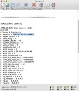
Before proceeding any further, we can’t stress enough the need to check the firmware version of your X-Nucleo IDW01M1 Wi-Fi module. The process is extremely simple, and will require you to go through a terminal emulator, like Tera Term Pro on Windows, or CoolTerm on macOS.
Place the X-Nucleo IDW01M1 onto the Nucleo F401RE, and plug the latter to your PC, then locate the storage volume NODE_F401RE. Any time you’ll want to upload an application onto your Nucleo board, the only thing you will have to do is drag and drop the binary into that volume, then wait for it to reboot automatically. Your LEDs on the Nucleo board will blink, which signals that the software has loaded. Just press the reset button on the F401RE, and the application will start.
At this stage, we’ll use an application that will help us determine the firmware version of the X-Nucleo IDW01M1. Just download the X-CUBE-WIFI1 software stack, then open the following folders: STM32CubeExpansionWIFI1_V2.1.1 -> Multi -> Applications -> WiFi_VCOM -> Binary -> STM32F401RE-Nucleo. The only step left is to drag the file Project.bin onto the NODE_F401RE volume, and wait for the lights to blink.
We must now open the terminal emulator and establish a connection with the Nucleo Board (usually COM3 or COM4 on Windows, if unsure, check Device Manager) using the following settings : Baud: 115200, Data: 8 bit, Parity: None; Stop Bit: 1 bit, Flow Ctrl: None and Localecho : on. Once the connection is open, press the reset button on the F401RE. When the program is available, and it appears on your terminal window, type AT+S.STS, and press Enter. A list of parameters will be printed. Scroll at the top to find “version”. If the value starts with 160129, you have the latest firmware, and you can proceed to the next step (1.3.3 Moving a 0-ohm resistance on the Wi-Fi Module). If it’s not, you absolutely need to update before proceeding.
1.3.2 Updating the Wi-Fi Module’s firmware
This step is very straight forward, but it will require you to use Windows. It’s the only process in this tutorial that can’t work on another operating system. The first task is to load the program for your Nucleo F401RE that will ensure the firmware of your Wi-Fi board becomes flashable. Open the following folders (from the X-CUBE-WIFI1 software stack) STM32CubeExpansion_WIFI1_V2.1.1 -> Projects -> Applications -> FW_Upgrade_UART -> Binary -> STM32F401RE-Nucleo, then drag and drop Project.bin onto the NODE_F401RE volume. Once the lights blinked, disconnect your board from your PC.
On X-Nucleo IDW01M1, install a jumper on JP2, to put the board into firmware download mode. You’ll then download and install Flasher-STM32, which is the utility designed to flash the firmware onto the board. The latest code can be found and downloaded on the STSW-WIFI001 page. Open the folders STSW-WIFI001 -> Rel. 3.5 -> BIN, then locate the file SPWF01S-160129-c5bf5ce-RELEASE-main.bin. You will need it when it is time to flash the new firmware.
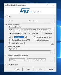
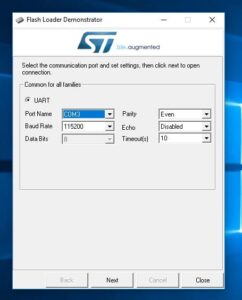
To install the latest firmware, connect the Nucleo board, with the X-Nucleo IDW01M1 attached, to your PC, and press the SW1 button found at the bottom right corner of the Wi-Fi module. Open the Flash Loader application previously installed – Flasher-STM32 is called Demonstrator GUI once installed – and choose the following options : the COM number of your board, usually COM3, Baud : 115200, Data Bits : 8 bits, Parity : Even, Echo : Disabled, Timesout: 10, then click Next. At this point:
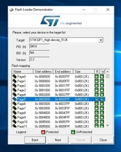
- You’ll see the Target is readable. Just click Next
- Select Page 5 0x8002800 (DOUBLE CHECK AS A MISSTEP COULD BRICK YOUR DEVICE), and click Next
- Choose Download from File and select the firmware previously located (SPWF01S-160129-c5bf5ce-RELEASE-main.bin), then select @h 8002800 (BE CERTAIN), and click Next
Note : Do not check the option to “Verify after download”, because a bug will trigger a false error.
If you want to make sure everything upgraded properly, follow the steps in 1.3.1 Checking the Wi-Fi Module’s firmware to ensure your version now starts with “160129”.
1.3.3 Moving a 0-ohm resistance on the Wi-Fi Module’s firmware
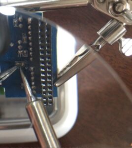
At the back of the X-Nucleo IDW01M1, you will notice a 0-ohm resistance on path R4. Before proceeding any further, and after you checked your firmware version, and upgraded if necessary, move that resistance to path R34. The process is relatively simple and will only require a soldering iron, some soldering wire, a wick, and flux if desired. Once this is done, you’re ready to build your first 6LoWPAN network.
Step 2. Creating the Gateway
At this point, you’ll need to create a gateway as the foundation of your network. Assemble your module by putting the X-Nucleo IDW01M1 on top of the Nucleo-F401RE, then the X-Nucleo IDS01A5 on top of the Wi-Fi board. The module can be placed anywhere, as long as it’s within range of the sub-gigahertz node and your Wi-Fi access point.
2.1 Setting Up Your Gateway
Connect the module to your PC, and locate the demo program (from FP-NET-6LPWIFI1) in STM32CubeFunctionPack_6LPWIFI1_V1.1.0 -> Projects -> Multi -> Applications -> WiFi-Bridge -> Binary -> STM32F401RE-Nucleo -> STM32F4xx-Nucleo-WiFi-Bridge-IDS01A5.bin. Move it to your Nucleo F401RE volume, and wait for the lights to blink.
Open a connection to the serial line with your Terminal Emulator (Baud Rate = 115200, Parity = None, Bits = 8, Stopbits = 1), then press the reset button on your Nucleo board.
The program will ask if you want to enter your Wi-Fi network’s settings. If you do nothing – or press “n” -, it will default to a Wi-Fi network with SSID “STM”, and a WPA2 password “STMdemoPWD”.
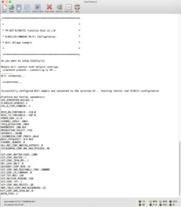
To enter your settings, press “y” in your Terminal Emulator. At this point, the module will scan the surrounding Wi-Fi networks and print a list of all the SSIDs it was able to scan. If you don’t see yours, although you’re supposed to, something may be wrong with your Wi-Fi Access Point. Make sure it is a 2.4 GHz network, and that the SSID is “broadcasted”, by checking your router’s setup. If you are sure that your Wi-Fi network is OK, or if you see your Wi-Fi network in the printed list, enter the name of your SSID. Sometimes, entering the SSID, even if it’s not found on the list, will also work. The next step is to key-in your password. If your network doesn’t use a password just enter a letter anyway. No matter what, the system will not allow you to leave that field blank. Finally, choose the correct encryption standard. If your network doesn’t require a password, type “0” and the system will ignore the password. Otherwise, type “1” for WEP, or “2” for WPA/WPA2.
If everything went well, you will see the message “Successfully configured WiFi module and connected to the selected AP” and a list of values.
2.2 Tips and tricks for an Autonomous Gateway
By default, the demo requires that you setup your gateway, leave it connected to your PC, then setup your node. As your settings are not written in memory, unplugging your gateway will require you to run through the setup in 2.1 again. However, if you wish to use the demo program and be able to unplug your module from the power source, the software was designed to automatically connect to a default Wi-Fi network (SSID: “STM”, WPA2 Password: “STMdemoPWD”) after a period of inactivity. Hence, there are two ways one could easily create a gateway that can function without necessarily being setup beforehand:
- You could import the demo’s source files to your toolchain, update the default Wi-Fi network values to match your access point, and load the application onto your board, but this is outside of scope of this demo.
- You could also create a network that matches the default values used by the program, which will then connect to it automatically.
Step 3. Creating the Node
The last step of this tutorial will walk you through building your node, meaning the module that will sense its environment and send the data to the Internet using the gateway we just built. Assemble your module by putting the X-Nucleo IDS01A5 on top of the Nucleo-F401RE, then place the X-Nucleo IKS01A2 on top of the IDS01A5.
3.1 Setting Up Your Node
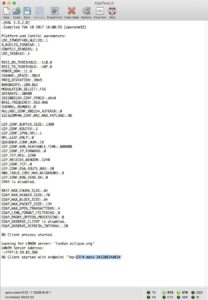
Connect the module to your PC, and locate the program (from FP-SNS-6LPNODE1) in STM32CubeFunctionPack_6LPNODE1_V1.1.0 -> Projects -> Multi -> Applications -> ipso-mems -> Binary -> STM32F401RE-Nucleo -> ipso-mems-IKS01A2-IDS01A5_f401.bin, then move it to the Nucleo F401RE volume, and wait for the LEDs to blink.
Open a connection to the serial line with your Terminal Emulator (Baud Rate = 115200, Parity = None, Bits = 8, Stopbits = 1), then press the reset button on your Nucleo board.
If everything went well, you should see a line that says, “RD Client process started.” After a few seconds, you’ll see a message such as “RD Client started with endpoint ‘?ep=STF4-mems-[string_of_numbers]’”. In our case, it was “STF4-mems-34328034A034”. It is important to note that identifier as we’ll need it later.
The string “STF4-mems-[string_of_numbers]” is unique to all devices and set in the firmware. You can therefore reinstall the demo program, or lose power, and that identifier will remain the same.
3.3 Working With Your Node
The demo program automatically sends the sensors’ data to a cloud server. To access it simply go to http://leshan.eclipse.org/#/clients and locate your module’s ID under “Client Endpoint”.
Clicking on your identifier will open a window with a list of values. To monitor the mouvements of your X-Nucleo IKS01A2 sensor board, go to the section called “Accelerometer”, and click “Observe” next to “X Value”, “Y Value”, and Z”Value”. You will see numbers appearing. Moving your node will automatically update them, showing that the system can now track of your movements using your sub-gigahertz network.
3.4 Tips and Tricks for Creating Your First Application
Leshan is not designed for production code and mass market applications. However, it is possible to use their API to automatically get the values from the node to your application, so you can start developing a very simple program, thanks to a very well thought-out URL scheme, designed by the OMA LightweightM2M (LwM2M) standard, which takes the form of “/Object ID/Instance Number/Resource ID”.
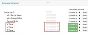
In Leshan, the page used to monitor the values from the node’s gyroscope is found at http://leshan.eclipse.org/#/clients/STF4-mems-[string_of_numbers], or in our case http://leshan.eclipse.org/#/clients/STF4-mems-34328034A034. Next to the X Value in the Accelerometer section, is a path called “/3313/0/5702”, which will remain the same, no matter your ID.
Hence, if you replace the “#” with “api” in the url, and add the path for the X Value, you can get the string containing the measurement. In our example, typing “http://leshan.eclipse.org/api/clients/STF4-mems-34328034A034/3313/0/5702” in a browser will return the string: “{“status”:”CONTENT”,”content”:{“id”:5702,”value”:-0.1025390625}}”, the number after “value” being the sensor’s data.
As are result, one could create a program with a simple loop to get the X (/3313/0/5702), Y (/3313/0/5703), and Z (/3313/0/5704) values from the Leshan servers. by using their API and URL scheme, which means, you have not only setup your sub-gigahertz network, but have created the foundation for your first project.
